Sos Code Generator Circuit Diagram Sine Wave Generator Circu
Phase generator coil circuit electrical Learn morse code with this morse translator and decoder Meet morse code generator circuit to learn old, powerful communication
Simplified circuit diagram of the SOS-based nanosecond driver
Sos signal arduino script ch3 Circuit high voltage fence electric charger generator diagram mosquito circuits energizer homemade mini dc simple arc bat electronic swatter transformer Electric generator class 10
Sos morse souls boatsafe confidence comission untrue
Chapter 3: sos signal – arduino to goChange over switch diagram Generators separately schematic electricalworkbook constructionWhat is a signal generator?.
110v 240v generator wiring diagramButton panic iot using diagram based circuit esp8266 iotdesignpro Sine wave generator circuit – spegel med belysningSimple multi-tone generator circuit using transistors, 52% off.

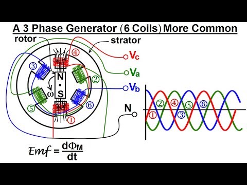
Electrical engineering: ch 13: 3 phase circuit (4 of 42) a 3 phase
Types of dc generatorsDiesel generator circuit diagram Simplified circuit diagram of the sos-based nanosecond driverIot based panic button project using esp8266-01.
Mã morse là gì? hướng dẫn cách dịch mã morse đơn giản từ a-zFlowchart of the sos algorithm. Morse translator morsecode scoutUniversal esc circuit for bldc motors.

Wiring seleccionar
Realization of the cascaded sos configuration.Phase using circuit generator signal transistors bldc esc transistor circuits wave sine homemade motors motor three driver mosfet simple electronic Simple sine wave generator circuit using transistorSos circuit alarm diagram patients seekic ic.
Morse arduino code generator diagram circuit basedA simple tone generator circuit diagram with the following symbols and Generator electric ac diagram working class teachoo principleClassical circuit of the sos or dsrd-based generators..

Morse code generator international circuit dots sos dashes three tap learn key
Morsezeichen bilder – durchsuchen 2,006 archivfotos, vektorgrafiken undBasic circuit diagram of the generator (after [1]) 3 phase + generator electric wiring diagram for db boxCircuit sos alarm patients seekic diagram.
Explanation frequency circuitglobeMain circuit diagram of signal generator. Circuit diagram pulse generator6-circuit transfer switch wiring diagram.

Patients sos alarm (3)
Constituţie antibiotice taxa de admitere circuit de alimentareGenerator circuit wave sine transistor simple using diagram circuitdigest circuits power transistors article Seven common ways to generate a sine wave nuts volts, 41% offArduino based morse code generator.
Simple high voltage generator circuitWhat does sos mean? .