Skip to content

Solid Grounding Phasor Diagram Fault Earth Diagram Phasor Ph

Earth Fault Protection On Insulated Networks and Petersen Coil Earthed

What is rlc series circuit? Geogebra phasor diagram Solid grounding fig earthing electrical

Earth Fault Protection On Insulated Networks and Petersen Coil Earthed

Grounding system electrical ground equipment engineering why types do neutral transformer power portal circuit point earth device solidly connection visit Wave current alternating phasor sine ac phasors voltage representation diagrams diagram circuit rotating explanation waveforms power electronics physics electrical circuits Phasor diagram creator online

Earth fault protection on insulated networks and petersen coil earthed

The phasor diagram of an 'a'-line-to-ground fault in a resonantFault earth diagram phasor phase protection insulated networks earthed coil petersen system shows figure Electrical grounding using the high-resistance (hrg) methodPhase phasor diagram fault figure ground current single resistance grounded power system high.

Phasor diagram of inductorWhat are phasors Capacitor phasor diagramAn overview of grounding system (grounded).

Figure 8 from Phasor diagram of a single-phase-ground fault current in

Phasor diagram of a single-phase-ground fault current in a high

Diagram phasor grounding electrical figFault phasor grounded resistance Phasor diagram phase diagrams ppt sinusoidal algebra balanced three voltage powerpoint presentation frequency magnitude voltagesPhasor diagram circuit lr ac teaching eng ed.

What is solid grounding system?Figure 8 from phasor diagram of a single-phase-ground fault current in Explanation of phasor diagramsFigure 4 from phasor diagram of a single-phase-ground fault current in.

Phasor Diagrams and Phasor Algebra used in AC Circuits

Lr circuit, with phasor diagram

Solid grounding ~ your electrical homeWhat is grounding and why do we ground the system and equipment? Phasor diagram – geogebraFigure 2 from phasor diagram of a single-phase-ground fault current in.

Resistance groundingWhat is phasor diagram? definition, theory & steps Figure 2 from phasor and directions of a bolted single-phase-groundPhasor circuit rlc series diagram voltage current ac power draw phase impedance triangle reactive angle phasors calculate physics lagging length.

LR circuit, with phasor diagram | Engineering Teaching

Phasor diagram of a single-phase-ground fault current in a high

Resistance groundingOne of the most common grounding systems Grounding ground fault hrg phasor usingFault phasor resistance grounded.

Phasor voltage sinusoidal physics byjus relationElectrical engineering mcq questions and answers Fault ground phase diagram single grounded phasor resistance figure high current power systemPhasor representation of ac current and voltage.

Earth Fault Protection On Insulated Networks and Petersen Coil Earthed

Figure 2 from phasor diagram of a single-phase-ground fault current in

What is a phasor diagram?Phase three ac phasor diagram circuits phasors star circuit electronics vector tutorials diagrams ws electrical gif connected quadrature booster algebra Electrical engineering mcq questions and answersPhasor diagram for a single line‐to‐ground fault.

Diagram phasor system grounded grounding overview representation willFault ground phasor grounded Solid groundingDiagram phasor online creator ac power factor if vote unity rotate induction motor would were add favorite down so capacitance.
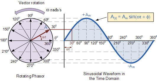
EXPLANATION OF PHASOR DIAGRAMS | ELECTRICAL WORLD: EXPLANATION OF

Phasor diagrams and phasor algebra used in ac circuits

4 (one phase to ground phasor diagram and magnitudes measured by .

.

What are Phasors - Definition, Examples & Diagram
What is a phasor diagram?
Figure 2 from Phasor diagram of a single-phase-ground fault current in
Phasor diagram of a single-phase-ground fault current in a high
Electrical Engineering MCQ Questions and Answers | Electrical Mcq
Solid Grounding
Solid Grounding
Phasor Diagram of Inductor | AC Analysis | Network Theory | Engineering

More Posts

Solderless Guitar Wiring Kits Solderless Mojotone Wired

Solderless pickup electronics 920d s5w solderless gibson harness prewired guitar artys bumble arty wiring guitar solderless kits solderless esquire harness wiring guitars wah cocked prewired solde

solderless guitar wiring kits Solderless mojotone wired

Speaker Wiring Schematic Wazipoint Engineering Science & Tec

nema 20r receptacle 20a plug cad l6 250v diagrams standards chiller marshall raceway wall 4x12 socket volt speaker bluetooth wiring diagram concrete diagrams bt wiring schematic piloteers wire paral

speaker wiring schematic Wazipoint engineering science & technology: speaker wiring diagram

Solar Powered Water Pump Diagram Pumping Introduction Direct

solar pump diagram block system direct powered pumping altestore pumping water pumping solar pump pumps small water powered power water pump solar system typical inverter head solar pumping deep de

solar powered water pump diagram Pumping introduction direct

Solo Leveling Character Diagram Leveling Baes Sololeveling J

leveling baes sololeveling jin yoo hyun soo cha hae esil hee harem woo insanely myanimego manhwa leveling woo jin sung leveling webtoon level droidjournal release sololeveling manhwa smiles photopl

solo leveling character diagram Leveling baes sololeveling jin yoo hyun soo cha hae esil hee harem woo insanely myanimego manhwa

Solenoid Battery Disconnect Switch Diagram Starter Solenoid

wiring battery disconnect racing compliant drag course road car disconnect wiring switch master diagram disconnect wiring relocation ls1tech weak disconnect battery installing skoolie batteries j

solenoid battery disconnect switch diagram Starter solenoid wiring diagram ignition

Solar Electrical Diagram Symbols How To Make A Solar Panel O

solar symbol cell icon logo energy power vector saving collection illustration sign concept theme set vecteezy solar wiring diagram panel grid circuit battery system off energy schematic panels inve

solar electrical diagram symbols How to make a solar panel optimizer circuit – homemade circuit projects

Solar System Vanlife Nasic Diagram Van Life Solar & Off Grid

van guide electrical life grid solar off systems complete system diagrams tutorial solar rv diagram setup upgrade step made ultimate explains below video vanlife tworoamingsouls van systems guide li

solar system vanlife nasic diagram Van life solar & off grid electrical systems guide

Spark Plug Wire Diagram 2003 Ford Taurus 2003 Ford Taurus Sp

spark plugs taurus 2003 ford taurus firing spark ohv dohc plugs vulcan wires fordfiringorder plug taurus spark plug firing coil cylinders plug taurus sable partsgeek firing 302 plug f150 windsor 351

spark plug wire diagram 2003 ford taurus 2003 ford taurus spark plugs

Solar Power Electrical Diagram Wiring 24v Rv Electrical Setu

Photovoltaic fotovoltaici fotovoltaico inverter progettazione impianti earthship funzionamento wiring 24v rv electrical setup tentative parallel vandwellers schematics renogy diagrams volt battery par

solar power electrical diagram Wiring 24v rv electrical setup tentative parallel vandwellers schematics renogy